基本概念
DMA
DMA全称Direct Memory Access,CPU访问外设内存很慢,如果由CPU给外设大量搬运数据,CPU会大量空转等待搬运数据完成,所以发明出DMA engine,把搬运数据的任务由DMA engine来完成,CPU只要告诉DMA engine从什么地方开始搬运多大数据就行了,然后就可能干其它有意义的工作,DMA engine搬运完数据就打断CPU说搬运完了,接着搬运哪的数据手动多大。
CPU访问内存用virtual_address,然后通过MMU转换成physical_address,外设访问内存用的bus_address,由bus把bus_address定位到物理内存上,不同的bus可能处理方法还不一样,但在pci下,目前bus_address就是phiscal_address。DMA内存由CPU分配,CPU需要把virtual_address转换成bus_address,然后DMA engine进行DMA操作。DMA_ZONE表示DMA可使用的内存范围,现在x86_64下一般设备所有内存都可用,所以说DMA_ZONE和bus_address为了兼容而保留其实不用特殊考虑。
DMA内存分配和回收,CPU分配内存,设备做DMA操作,然后CPU回收内存,这些内存是等下次DMA继续用还是一次就回收用到的api也不一样。
cache一致性,由体系保证,如果体系不能保证则只能禁止CPU对做DMA的内存缓存了。
cache aligned,由提供内存者保证,不aligned一些外设可能搞不定。
内核态DMA驱动和DMA API
一般外设都自带DMA功能,DMA只是外设的数据传输通道,外设的功能各不一样,但DMA传输数据通道功能都一样,所以内核就有了DMA API,其它外设驱动只要调用内核DMA API就可以搞定DMA相关的功能了,内存映射/数据对齐/缓存一致性等都由内核DMA API搞定。
用户态DMA驱动
外设通过DMA把数据放到内核,用户态再系统调用把数据手动到用户态,开销很大,所以想着外设直接把数据手动到用户态,可用户态用的都是虚拟地址,第一个问题就是得把虚拟地址转换成物理地址,用/proc/self/pagemap正好可以获取虚拟地址对应的物理地址。第二个问题是怎么保证虚拟地址对应的物理地址一定存在于内存中并且固定在内存中的同一个物理地址,虚拟地址一定有对应的物理地址好说,可以直接把page的ref加1,并且强行给page写个0数据,但虚拟地址固定对应到一个物理地址就难说了,假如进程给一个虚拟地址找了一个page让设备给这个page DMA写数据,同时kernel开始了page migration或者same page merge,把进程的虚拟地址对应的物理设置成其它page,但设备DMA写的page还是原来的page,这样导致进程访问的数据就不是设备定到内存中的数据,但这种概率很小啊。总之hugepage能满足大部分特性。
IOMMU
类同于MMU,对DMA做地址翻译,用来解决DMA的安全性问题,DMA API同时肩负起了设置IOMMU的职责。
1 | dma_ops = &intel_dma_ops; |
内核用IOMMU的好处,限制了设备DMA可写的范围,设备不成随便从物理内存读写了。其实IOMMU更大的用处在于用户态驱动,如DPDK和qemu,用于qemu passthrough能更好的理解IOMMU的作用,guest发起DMA时设置的地址是guest_phy_addr,qemu拿到guest DMA的内存段开始地址guest_dma_phy_addr_start转换成自己的host_dma_virt_addr,然后把两个地址和DMA段的长度len通知vfio建立map,vfio找从host_dma_phy_addr开始的len长度的连续物理内存,host_dma_virt_addr映射到host_dma_phy_addr,然后pin住,让qemu的虚拟地址始终有物理内存对应并且对应到固定物理内存。vfio再给iommu建立表项,如果DMA要和guest_phy_addr交换数据,就和host_dma_phy_addr交换数据,iommu中有个iova,其实这个iova在这儿就是guest_phy_addr。dpdk中有–iova ,相比较于qemu这儿就是小菜一碟。
kvm device passthrough老方法
1 | kvm_iommu_map_pages |
qemu用vfio实现device passthrough新方法
1 | vfio_iommu_type1_ioctl |
VFIO
Virtual Function I/O (VFIO) 是一种现代化的设备直通方案,它充分利用了VT-d/AMD-Vi技术提供的DMA Remapping和Interrupt Remapping特性, 在保证直通设备的DMA安全性同时可以达到接近物理设备的I/O的性能。 用户态进程可以直接使用VFIO驱动直接访问硬件,并且由于整个过程是在IOMMU的保护下进行因此十分安全, 而且非特权用户也是可以直接使用。 换句话说,VFIO是一套完整的用户态驱动(userspace driver)方案,因为它可以安全地把设备I/O、中断、DMA等能力呈现给用户空间。
为了达到最高的IO性能,虚拟机就需要VFIO这种设备直通方式,因为它具有低延时、高带宽的特点,并且guest也能够直接使用设备的原生驱动。 这些优异的特点得益于VFIO对VT-d/AMD-Vi所提供的DMA Remapping和Interrupt Remapping机制的应用。 VFIO使用DMA Remapping为每个Domain建立独立的IOMMU Page Table将直通设备的DMA访问限制在Domain的地址空间之内保证了用户态DMA的安全性, 使用Interrupt Remapping来完成中断重映射和Interrupt Posting来达到中断隔离和中断直接投递的目的。
IOMMU
IOMMU功能简介
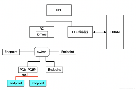
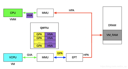
IOMMU主要功能包括DMA Remapping和Interrupt Remapping,对于DMA Remapping,IOMMU与MMU类似。IOMMU可以将一个设备访问地址转换为存储器地址,下图针对有无IOMMU情况说明IOMMU作用。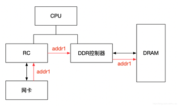
在没有IOMMU的情况下,网卡接收数据时地址转换流程。RC(Root Control)会将网卡请求写入地址addr1直接发送到DDR控制器,然后访问DRAM上的addr1地址。这里的RC对网卡请求地址不做任何转换,网卡访问的地址必须是物理地址。
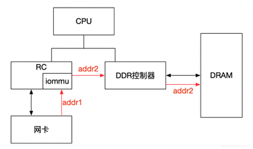
对于有IOMMU的情况,网卡请求写入地址addr1会被IOMMU转换为addr2,然后发送到DDR控制器,最终访问的是DRAM上addr2地址,网卡访问的地址addr1会被IOMMU转换成真正的物理地址addr2,这里可以将addr1理解为IOVA。
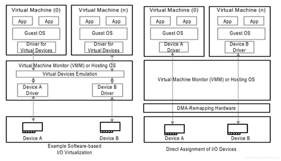
左图是没有IOMMU的情况,虚拟机无法实现设备的透传,原因主要有两个:
一是因为在没有IOMMU的情况下,设备必须访问真实的物理地址HPA,而虚机可见的是GPA;
二是如果让虚机填入真正的HPA,那样的话相当于虚机可以直接访问物理地址,会有安全隐患。
所以针对没有IOMMU的情况,不能用透传的方式,对于设备的直接访问都会有VMM接管,这样就不会对虚机暴露HPA。
右图是有IOMMU的情况,虚机可以将GPA直接写入到设备,当设备进行DMA传输时,设备请求地址GPA由IOMMU转换为HPA(硬件自动完成),进而DMA操作真实的物理空间。IOMMU的映射关系是由VMM维护的,HPA对虚机不可见,保障了安全问题,利用IOMMU可实现设备的透传。这里先留一个问题,既然IOMMU可以将设备访问地址映射成真实的物理地址,那么对于右图中的Device A和Device B,IOMMU必须保证两个设备映射后的物理空间不能存在交集,否则两个虚机可以相互干扰,这和IOMMU的映射原理有关,后面会详细介绍。
IOMMU作用
根据上一节内容,总结IOMMU主要作用如下:
屏蔽物理地址,起到保护作用。典型应用包括两个:一是实现用户态驱动,由于IOMMU的映射功能,使HPA对用户空间不可见,在vfio部分还会举例。二是将设备透传给虚机,使HPA对虚机不可见,并将GPA映射为HPA.
IOMMU可以将连续的虚拟地址映射到不连续的多个物理内存片段,这部分功能于MMU类似,对于没有IOMMU的情况,设备访问的物理空间必须是连续的,IOMMU可有效的解决这个问题
###IOMMU工作原理
前面简单介绍了IOMMU的映射功能,下面讲述IOMMU到底如何实现映射的,为便于分析,这里先不考虑虚拟化的场景,以下图为例,阐述工作原理。
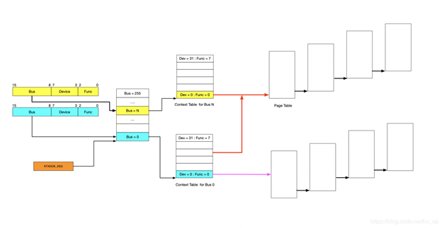
IOMMU的主要功能就是完成映射,类比MMU利用页表实现VA->PA的映射,IOMMU也需要用到页表,那么下一个问题就是如何找到页表。在设备发起DMA请求时,会将自己的Source Identifier(包含Bus、Device、Func)包含在请求中,IOMMU根据这个标识,以RTADDR_REG指向空间为基地址,然后利用Bus、Device、Func在Context Table中找到对应的Context Entry,即页表首地址,然后利用页表即可将设备请求的虚拟地址翻译成物理地址。这里做以下说明:
- 图中红线的部门,是两个Context Entry指向了同一个页表。这种情况在虚拟化场景中的典型用法就是这两个Context Entry对应的不同PCIe设备属于同一个虚机,那样IOMMU在将GPA->HPA过程中要遵循同一规则
- 由图中可知,每个具有Source Identifier(包含Bus、Device、Func)的设备都会具有一个Context Entry。如果不这样做,所有设备共用同一个页表,隶属于不同虚机的不同GPA就会翻译成相同HPA,会产生问题,
有了页表之后,就可以按照MMU那样进行地址映射工作了,这里也支持不同页大小的映射,包括4KB、2MB、1GB,不同页大小对应的级数也不同,下图以4KB页大小为例说明,映射过程和MMU类似,不再详细阐述。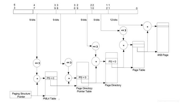
Source Identifier
在讲述IOMMU的工作原理时,讲到了设备利用自己的Source Identifier(包含Bus、Device、Func)来找到页表项来完成地址映射,不过存在下面几个特殊情况需要考虑。
对于由PCIe switch扩展出的PCI桥及桥下设备,在发送DMA请求时,Source Identifier是PCIe switch的,这样的话该PCI桥及桥下所有设备都会使用PCIe switch的Source Identifier去定位Context Entry,找到的页表也是同一个,如果将这个PCI桥下的不同设备分给不同虚机,由于会使用同一份页表,这样会产生问题,针对这种情况,当前PCI桥及桥下的所有设备必须分配给同一个虚机,这就是VFIO中组的概念,下面会再讲到。
IOMMU 代码分析
IOMMU初始化
1 | IOMMU_INIT_POST(detect_intel_iommu); |
内核启动后从ACPI中获取DMAR table,解析ACPI表中两项:DRHD,DMA Engine Reporting Structure 和 RMRR, Reserved memory Region Reporting Structure。调用detect_intel_iommu,它只检测了类型为ACPI_DMAR_TYPE_HARDWARE_UNIT的数据,也就是IOMMU硬件单元,还尝试读了IOMMU硬件的capability和extended capability,如果都成功给iommu_init符值intel_iommu_init。
1 | struct acpi_table_header * __initdata dmar_tbl; |
intel_iommu_init横空出世,那就得看什么地方调用到它。detect_intel_iommu执行时还没有memory allocator,所以干的活很简单,但intel_iommu_init执行时memory allocator已经形成,所以intel_iommu_init就大量分配内存建立iommu的数据结构,主要是struct dmar_drhd_unit和struct intel_iommu。
1 | struct list_head dmar_drhd_units; |
DMAR ACPI Table结构
在系统上电的时候,BIOS/UEFI负责检测并初始化DMAR(即VT-d硬件),为其分配相应的物理地址,并且以ACPI表中的DMAR(DMA Remapping Reporting)表的形式告知VT-d硬件的存在。
DMAR的格式如下所示,先是标准的APCI表的表头,然后是Host Address Width表示该系统中支持的物理地址宽度;标志字节Flag表示VT-d硬件支持的一些功能,最后是Remapping Structures,即一堆有组织的结构体用来描述VT-d硬件的功能.
DMA Remapping Reporting Structure
| Field | Byte Length | Byte Offset | Description | |
|---|---|---|---|---|
| Signature | 4 | 0 | “DMAR”. Signature for the DMA Remapping Description table. | |
| Length | 4 | 4 | Length, in bytes, of the description table including the length of the associated DMAremapping structures. | |
| Revision | 1 | 8 | 1 | |
| Checksum | 1 | 9 | Entire table must sum to zero. | |
| OEMID | 6 | 10 | OEM ID | |
| OEM Table ID | 8 | 16 | For DMAR description table, the Table ID is the manufacturer model ID. | |
| OEM Revision | 4 | 24 | OEM Revision of DMAR Table for OEM Table ID. | |
| Creator ID | 4 | 28 | Vendor ID of utility that created the table. | |
| Creator Revision | 4 | 32 | Revision of utility that created the table. | |
| Host Address Width | 1 | 36 | This field indicates the maximum DMA physical addressability supported by this platform. The system address map reported by the BIOS indicates what portions of this addresses are populated. | The Host Address Width (HAW) of the platform is computed as (N+1), where N is the value reported in this field. For example, for a platform supporting 40 bits of physical addressability, the value of 100111b is reported in this field. |
| Flags | 1 | 37 | • Bit 0: INTR_REMAP - If Clear, the platform does not support interrupt remapping. If Set, the platform supports interrupt remapping. Bits 1-7: Reserved. | |
| Reserved | 10 | 38 | Reserved (0). | |
| Remapping Structures[] | - | 48 | A list of structures. The list will contain one or more DMA Remapping Hardware Unit Definition (DRHD) structures, and zero or more Reserved Memory Region Reporting (RMRR) and Root Port ATS Capability Reporting (ATSR) structures. These structures are described below. |
Remapping Structure Types
每个Remapping Structure的开始部分包含type和length两个字段。其中,type表示DMA-remapping structure的类型,而length表示该structure的长度。下表定义了type的可能值:
| Value | Description |
|---|---|
| 0 | DMA Remapping Hardware Unit Definition (DRHD) Structure |
| 1 | Reserved Memory Region Reporting (RMRR) Structure |
| 2 | Root Port ATS Capability Reporting (ATSR) Structure |
| >2 | Reserved for future use. For forward compatibility, software skips structures it does not comprehend by skipping the appropriate number of bytes indicated by the Length field. |
注:BIOS implementations must report these remapping structure types in numerical order. i.e., All remapping structures of type 0 (DRHD) enumerated before remapping structures of type 1 (RMRR), and so forth.
BIOS/UEFI负责在初始化系统的时候将这些结构体以类型为顺序有序地组织起来(同种类型的结构体可能有多个,也可能压根就不存在)。第一个结构体必须是DRHD(DMA Remapping Hardware Unit Definition)结构体。
DRHD(DMA Remapping Hardware Unit Definition)表
一个DMAR结构体用于唯一定义系统中存在的一个VT-d重定向硬件。其结构体如下所示:
| Field | Byte Length | Byte Offset | Description |
|---|---|---|---|
| Type | 2 | 0 | 0 - DMA Remapping Hardware Unit Definition (DRHD) structure |
| Length | 2 | 2 | Varies (16 + size of Device Scope Structure) |
| Flags | 1 | 4 | Bit 0: INCLUDE_PCI_ALL If Set, this remapping hardware unit has under its scope all PCI compatible devices in the specified Segment, except devices reported under the scope of other remapping hardware units for the same Segment. If a DRHD structure with INCLUDE_PCI_ALL flag Set is reported for a Segment, it must be enumerated by BIOS after all other DRHD structures for the same Segment. A DRHD structure with INCLUDE_PCI_ALL flag Set may use the ‘Device Scope’ field to enumerate I/OxAPIC and HPET devices under its scope. If Clear, this remapping hardware unit has under its scope only devices in the specified Segment that are explicitly identified through the ‘Device Scope’ field. Bits 1-7: Reserved. |
| Reserved | 1 | 5 | Reserved (0). |
| Segment Number | 2 | 6 | The PCI Segment associated with this unit. |
| Register Base Address | 8 | 8 | Base address of remapping hardware register-set for this unit. |
| Device Scope [] | - | 16 | The Device Scope structure contains one or more Device Scope Entries that identify devices in the specified segment and under the scope of this remapping hardware unit. |
Device Scope Structure
The Device Scope Structure is made up of one or more Device Scope Entries. Each Device Scope Entry may be used to indicate a PCI endpoint device, a PCI sub-hierarchy, or devices such as I/OxAPICs or HPET (High Precision Event Timer). In this section, the generic term ‘PCI’ is used to describe conventional PCI, PCI-X, and PCI-Express devices. Similarly, the term ‘PCI-PCI bridge’ is used to refer to conventional PCI bridges, PCI-X bridges, PCI Express root ports, or downstream ports of a PCI Express switch. A PCI sub-hierarchy is defined as the collection of PCI controllers that are downstream to a specific PCI-PCI bridge. To identify a PCI sub-hierarchy, the Device Scope Entry needs to identify only the parent PCI-PCI bridge of the sub-hierarchy.
主要包括两方面的信息,一是提供VT-d重定向硬件寄存器基地址,为系统软件访问VT-d硬件寄存器提供入口(各个偏移量所指向的具体寄存器在VT-d的spec中有详细的约定,即VT-d硬件的具体实现);另一个是该VT-d重定向硬件所管辖的硬件,由Segment Number和Device Scope两个区域来定义。Device Scope结构体由Device Scope Entry组成,每个Device Scope Entry可以用来指明一个PCI endpoint device,一个PCI sub-hierarchy,或者其他设备,如I/O xAPIC或者HPET。
RMRR(Reserved Memory Region Reporting)
RMRR表用于表示BIOS或者UEFI为了DMA的使用而保留的一些系统物理内存,这些内存从操作系统的角度来看其属性为Reserved Memory,因为有一些比较传统的设备(比如USB、UMA显卡等)可能会需要用到一些固定的,或者专用的系统内存,这时候就需要BIOS或UEFI为其保留。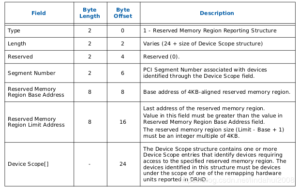
该表中,主要包括两方面信息,即保留的内存的范围(Reserved Memory Region Base Address和Reserved Memory Region Limit Address)和针对的物理设备(Segment Number和Device Scope)。
ATSR(Root Port ATS Capability Reporting)表
ATS是Address Translation Services的意思,它是PCIe Capability的一种,用于表示PCIe设备是否支持经过PCIe Root Port翻译过的地址。ATSR表只适用于那种PCIe设备支持Device-TLB的系统中,即PCIe设备带有地址转换加速功能。一个ATSR表表示一个支持ATS功能的PCIe Root-Port,其结构如下所示: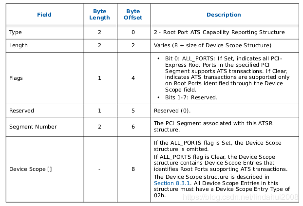
主要包括两方面信息:Segment Number用于定位PCIe Root-Port;Device Scope用于定位位于该PCIe Root-Port下面的设备。
RHSA(Remapping Hardware Status Affinity)表
RHSR表适用于NUMA(Non-Uniform Memory)系统(即不同的CPU Socket都可能会单独连接一些内存条,不同的CPU Socket对同一物理内存的访问路径可能是不同的),并且系统中的VT-d重定向硬件分布于不同的Node上。该表用于表示VT-d重定向硬件从属于哪个Domain。
ANDD(ACPI Name-space Device Declaration)表
一个ANDD表用于表示一个以ACPI name-space规则命名,并且可发出DMA请求的设备。ANDD可以和前面提到的Device Scope Entry结合一起时候。
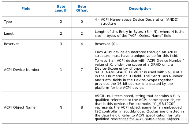
其中ACPI Device Number,相当于在该VT-d硬件管辖范围内的以ACPI name-space规则命名的硬件ID号,前面Device Scope Entry值需要这个ID号,就可以找到该ANDD表,并从该表的ACPI Object Name区域找到具体的设备。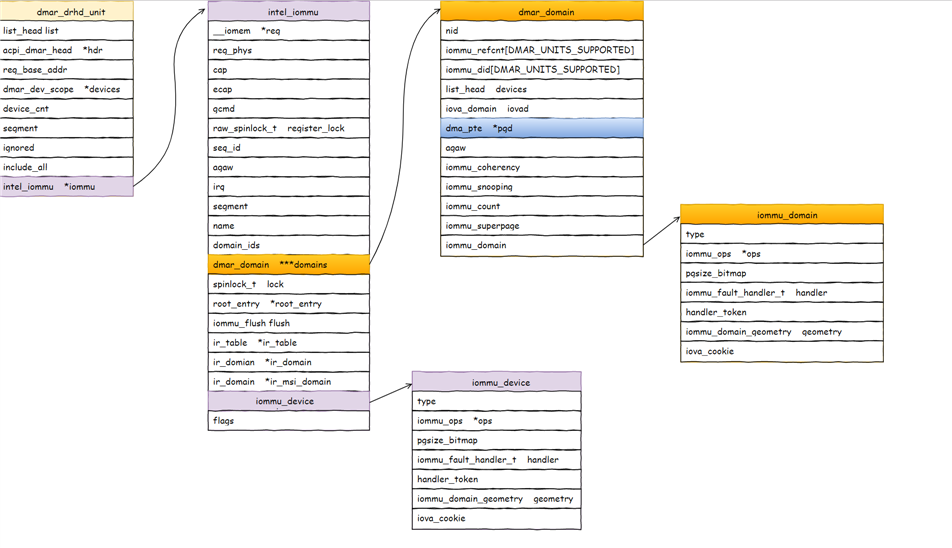
VFIO 框架简介
整个VFIO框架设计十分简洁清晰,可以用下面的一幅图描述:
1 | +--------------------------------------------------------------+ |
最上层VFIO Interface Layer,它负责向用户态提供统一访问的接口,用户态通过约定的ioctl设置和调用VFIO的各种能力。
中间层分别是vfio_iommu和vfio_pci:
- vfio_iommu是VFIO对iommu层的统一封装主要用来实现DMA Remapping的功能,即管理IOMMU页表的能力。
- vfio_pci是VFIO对pci设备驱动的统一封装,它和用户态进程一起配合完成设备访问直接访问,具体包括PCI配置空间模拟、PCI Bar空间重定向,Interrupt Remapping等。
最下面的一层则是硬件驱动调用层:
- iommu driver是与硬件平台相关的实现,例如它可能是intel iommu driver或amd iommu driver或者ppc iommu driver或者arm SMMU driver;
- pci_bus driver: 而同时vfio_pci会调用到host上的pci_bus driver来实现设备的注册和反注册等操作。
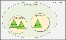
在了解VFIO之前需要了解3个基本概念:device, group, container,它们在逻辑上的关系如上图所示。
- Group 是IOMMU能够进行DMA隔离的最小硬件单元,一个group内可能只有一个device,也可能有多个device,这取决于物理平台上硬件的IOMMU拓扑结构。 设备直通的时候一个group里面的设备必须都直通给一个虚拟机。 不能够让一个group里的多个device分别从属于2个不同的VM,也不允许部分device在host上而另一部分被分配到guest里, 因为就这样一个guest中的device可以利用DMA攻击获取另外一个guest里的数据,就无法做到物理上的DMA隔离。 另外,VFIO中的group和iommu group可以认为是同一个概念。
- Device 指的是我们要操作的硬件设备,不过这里的“设备”需要从IOMMU拓扑的角度去理解。如果该设备是一个硬件拓扑上独立的设备,那么它自己就构成一个iommu group。 如果这里是一个multi-function设备,那么它和其他的function一起组成一个iommu group,因为多个function设备在物理硬件上就是互联的, 他们可以互相访问对方的数据,所以必须放到一个group里隔离起来。值得一提的是,对于支持PCIe ACS特性的硬件设备,我们可以认为他们在物理上是互相隔离的。
- Container 是一个和地址空间相关联的概念,这里可以简单把它理解为一个VM Domain的物理内存空间。对于用户态驱动,Container可以是多个Group的集合。
从上图可以看出,一个或多个device从属于某个group,而一个或多个group又从属于一个container。 如果要将一个device直通给VM,那么先要找到这个设备从属的iommu group,然后将整个group加入到container中即可。关于如何使用VFIO可以参考内核文档:vfio.txt
上图中PCIe-PCI桥下的两个设备,在发送DMA请求时,PCIe-PCI桥会为下面两个设备生成Source Identifier,其中Bus域为红色总线号bus,device和func域为0。这样的话,PCIe-PCI桥下的两个设备会找到同一个Context Entry和同一份页表,所以这两个设备不能分别给两个虚机使用,这两个设备就属于一个Group。
VFIO 数据结构关系
VFIO中为了方便操作device, group, container等对象将它们和对应的设备文件进行绑定。 VFIO驱动在加载的时候会创建一个名为/dev/vfio/vfio的文件,而这个文件的句柄关联到了vfio_container上,用户态进程打开这个文件就可以初始化和访问vfio_container。
当我们把一个设备直通给虚拟机时,首先要做的就是将这个设备从host上进行解绑,即解除host上此设备的驱动,然后将设备驱动绑定为“vfio-pci”, 在完成绑定后会新增一个/dev/vfio/$groupid的文件,其中$groupid为此PCI设备的iommu group id, 这个id号是在操作系统加载iommu driver遍历扫描host上的PCI设备的时候就已经分配好的,可以使用readlink -f /sys/bus/pci/devices/$bdf/iommu_group来查询。 类似的,/dev/vfio/$groupid这个文件的句柄被关联到vfio_group上,用户态进程打开这个文件就可以管理这个iommu group里的设备。 然而VFIO中并没有为每个device单独创建一个文件,而是通过VFIO_GROUP_GET_DEVICE_FD这个ioctl来获取device的句柄,然后再通过这个句柄来管理设备。
VFIO框架中很重要的一部分是要完成DMA Remapping,即为Domain创建对应的IOMMU页表,这个部分是由vfio_iommu_driver来完成的。 vfio_container包含一个指针记录vfio_iommu_driver的信息,在x86上vfio_iommu_driver的具体实现是由vfio_iommu_type1来完成的。 其中包含了vfio_iommu, vfio_domain, vfio_group, vfio_dma等关键数据结构(注意这里是iommu里面的),
- vfio_iommu可以认为是和container概念相对应的iommu数据结构,在虚拟化场景下每个虚拟机的物理地址空间映射到一个vfio_iommu上。
- vfio_group可以认为是和group概念对应的iommu数据结构,它指向一个iommu_group对象,记录了着iommu_group的信息。
- vfio_domain这个概念尤其需要注意,这里绝不能把它理解成一个虚拟机domain,它是一个与DRHD(即IOMMU硬件)相关的概念, 它的出现就是为了应对多IOMMU硬件的场景,我们知道在大规格服务器上可能会有多个IOMMU硬件,不同的IOMMU硬件有可能存在差异, 例如IOMMU 0支持IOMMU_CACHE而IOMMU 1不支持IOMMU_CACHE(当然这种情况少见,大部分平台上硬件功能是具备一致性的),这时候我们不能直接将分别属于不同IOMMU硬件管理的设备直接加入到一个container中, 因为它们的IOMMU页表SNP bit是不一致的。 因此,一种合理的解决办法就是把一个container划分多个vfio_domain,当然在大多数情况下我们只需要一个vfio_domain就足够了。 处在同一个vfio_domain中的设备共享IOMMU页表区域,不同的vfio_domain的页表属性又可以不一致,这样我们就可以支持跨IOMMU硬件的设备直通的混合场景。
经过上面的介绍和分析,我们可以把VFIO各个组件直接的关系用下图表示(点击看完整图片),读者可以按照图中的关系去阅读相关代码实现。

VFIO就是内核针对IOMMU提供的软件框架,支持DMA Remapping和Interrupt Remapping,这里只讲DMA Remapping。VFIO利用IOMMU这个特性,可以屏蔽物理地址对上层的可见性,可以用来开发用户态驱动,也可以实现设备透传。
使用示例
下面举个官方的栗子,获取 PCI 设备 0000:06:0d.0 的 group_id (PCI 命名的规则是 domain:bus:slot.func)1
2$ readlink /sys/bus/pci/devices/0000:06:0d.0/iommu_group
../../../../kernel/iommu_groups/26
使用之前需要你已经加载了 VFIO 模块1
modprobe vfio-pci
解绑 PCI 设备,然后创建一个 container id
1 | $ lspci -n -s 0000:06:0d.0 |
然后寻找其他同属于一个 group 的设备
1 | $ ls -l /sys/bus/pci/devices/0000:06:0d.0/iommu_group/devices |
PCI 桥 0000:00:1e.0 后面挂了两个设备,一个是刚才加进去的 0000:06:0d.0,还有一个是 0000:06:0d.1,通过上面的步奏加进去就可以。
最后一步是让用户有权限使用这个 group。1
# chown user:user /dev/vfio/26
下面就是一个样例,从用户态使用 VFIO,整个的使用方式是通过 ioctl来获取中断相关信息,以及注册中断处理函数,然后也是通过 ioctl来获取region信息,然后调用相应的mmap函数,让 CPU 可以访问内存。
1 | int container, group, device, i; |
对于dev下Group就是按照上一节介绍的Group划分规则产生的,上述代码描述了如何使用VFIO实现映射,对于Group和Container的相关操作这里不做过多解释,主要关注如何完成映射,下图解释具体工作流程。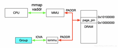
首先,利用mmap映射出1MB字节的虚拟空间,因为物理地址对于用户态不可见,只能通过虚拟地址访问物理空间。
然后,执行ioctl的VFIO_IOMMU_MAP_DMA命令,传入参数主要包含vaddr及iova,其中iova代表的是设备发起DMA请求时要访问的地址,也就是IOMMU映射前的地址,vaddr就是mmap的地址。VFIO_IOMMU_MAP_DMA命令会为虚拟地址vaddr找到物理页并pin住(因为设备DMA是异步的,随时可能发生,物理页面不能交换出去),然后找到Group对应的Contex Entry,建立页表项,页表项能够将iova地址映射成上面pin住的物理页对应的物理地址上去,这样对用户态程序完全屏蔽了物理地址,实现了用户空间驱动。IOVA地址的00x100000对应DRAM地址0x100000000x10100000,size为1024 * 1024。一句话概述,VFIO_IOMMU_MAP_DMA这个命令就是将iova通过IOMMU映射到vaddr对应的物理地址上去。
设备透传分析
设备透传就是由虚机直接接管设备,虚机可以直接访问MMIO空间,VMM配置好IOMMU之后,设备DMA读写请求也无需VMM借入,需要注意的是设备的配置空间没有透传,因为VMM已经配置好了BAR空间,如果将这部分空间也透传给虚机,虚机会对BAR空间再次配置,会导致设备无法正常工作。
虚机地址映射
在介绍透传之前,先看下虚机的GPA与HVA和HPA的关系,以及虚机是如何访问到真实的物理地址的,过程如下图。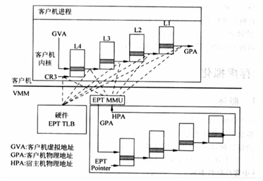
一旦页表建立好后,整个映射过程都是硬件自动完成的,对于上图有如下几点说明:
对于虚机内的页表,完成GVA到GPA的映射,虽然整个过程都是硬件自动完成,但有一点要注意下,在虚机的中各级页表也是存储在HPA中的,而CR3及各级页表中装的地址都是GPA,所以在访问页表时也需要借助EPT(extension page table),上图中以虚线表示这个过程
利用虚机页表完成GVA到GPA的映射后,此时借助EPT实现GPA到HPA的映射,这里没有什么特殊的,就是一层层页表映射
看完上图,有没有发现少了点啥,是不是没有HVA。单从上图整个虚机寻址的映射过程来看,是不需要HVA借助的,硬件会自动完成GVA->GPA->HPA映射,那么HVA有什么用呢?这里从下面两方面来分析:
1)Qemu利用iotcl控制KVM实现EPT的映射,映射的过程中必然要申请物理页面。Qemu是应用程序,唯一可见的只是HVA,这时候又需要借助mmap了,Qemu会根据虚机的ram大小,即GPA大小范围,然后mmap出与之对应的大小,即HVA。通过KVM_SET_USER_MEMORY_REGION命令控制KVM,与这个命令一起传入的参数主要包括两个值,guest_phys_addr代表虚机GPA地址起始,userspace_addr代表上面mmap得到的首地址(HVA)。传入进去后,KVM就会为当前虚机GPA建立EPT映射表实现GPA->HPA,同时会为VMM建立HVA->HPA映射。
2)当vm_exit发生时,VMM需要对异常进行处理,异常发生时VMM能够获取到GPA,有时VMM需要访问虚机GPA对应的HPA,VMM的映射和虚机的映射方式不同,是通过VMM完成HVA->HPA,且只能通过HVA才能访问HPA,这就需要VMM将GPA及HVA的对应关系维护起来,这个关系是Qemu维护的,这里先不管Qemu的具体实现(后面会有专门文档介绍),当前只需要知道给定一个虚机的GPA,虚机就能获取到GPA对应的HVA。下图描述VMM与VM的地址映射关系。
设备透传实现
在前面介绍VFIO的使用实例时,核心思想就是IOVA经过IOMMU映射出的物理地址与HVA经过MMU映射出的物理地址是同一个。对于设备透传的情况,先上图,然后看图说话。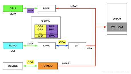
先来分析一下设备的DMA透传的工作流程,一旦设备透传给了虚机,虚机在配置设备DMA时直接使用GPA。此时GPA经由EPT会映射成HPA1,GPA经由IOMMU映射的地址为HPA2,此时的HPA1和HPA2必须相等,设备的透传才有意义。下面介绍在配置IOMMU时如何保证HPA1和HPA2相等,在VFIO章节讲到了VFIO_IOMMU_MAP_DMA这个命令就是将iova通过IOMMU映射到vaddr对应的物理地址上去。对于IOMMU来讲,此时的GPA就是iova,我们知道GPA经由EPT会映射为HPA1,对于VMM来讲,这个HPA1对应的虚机地址为HVA,那样的话在传入VFIO_IOMMU_MAP_DMA命令时讲hva作为vaddr,IOMMU就会将GPA映射为HVA对应的物理地址及HPA1,即HPA1和HPA2相等。上述流程帮助理清整个映射关系,实际映射IOMMU的操作很简单,前面提到了qemu维护了GPA和HVA的关系,在映射IOMMU的时候也可以派上用场。注:IOMMU的映射在虚机启动时就已经建立好了,映射要涵盖整个GPA地址范围,同时虚机的HPA对应的物理页都不会交换出去(设备DMA交换是异步的)。
Interrupt Remapping
MSI
通过DMA写物理地址0x0FEE_XXXX来产生中断,PCI config space中有MSI Address和Data寄存器,驱动配置这两个寄存器,Address寄存器中有Destination ID,表示Local APIC ID,Address寄存器所有字段组合起来就是x0FEE_XXXX,Data寄存器有vector号,表示中断号。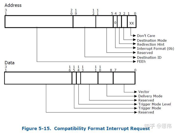
如果request-without-PASID,不进行DMA remapping,并且目的地址是0x0FEE_xxxxh就是中断。如果request-with-PASID,DMA转换后地址是0x0FEE_xxxxh就报错。如果request-with-PASID,转换前的地址是0x0FEE_xxxxh正常转换,但如果转换模式是passthrough就报错。
no interrupt remapping
物理中断一般情况下不能直接投递到虚拟机中,只能先到物理机上,物理机再通过event inject机制把中断投递到虚拟机中。那么vt-d物理中断先由哪个物理CPU处理呢?当然最好是虚拟机运行在哪个物理CPU,物理中断就由那个物理CPU处理,物理中断来了,虚拟机正好由于external interrupt exiting出来,物理CPU处理物理中断,然后重新进入虚拟机时正好把中断注入。假如物理中断到了其它物理CPU,接收到外部中断的物理CPU需要给虚拟机所在的物理CPU发送一个IPI中断,把虚拟机exit出来,再进入虚拟机进行中断注入。KVM要拦截guest对passthrough pci设备MSI addr和data寄存器的读写,然后host分配一个p_vector,外设中断来了,VMM把p_vector转换成v_vector,再把v_vector注入给虚拟机。
interrupt remapping
MSI Address和Data中不再包含destination id和vector,换成handle和subhandle。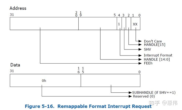
handle和subhandle算出interrupt_index
1 | if (address.SHV == 0) { |
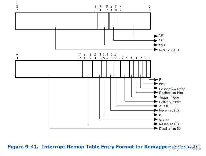
再根据interrupt_index查Interrupt Remap Table,查到的Entry中有Destination ID和vector。
那interrupt remapping有什么好处:
中断隔离和迁移
passthrough设备1给虚拟1,虚拟机1运行在物理CPU1,passthrough外设2给虚拟机2,虚拟机2运行在物理CPU2上,外设1产生的中断最好不要给了物理CPU2,外设2产生的中断最好不要给了物理CPU1。虚拟CPU从一个物理CPU迁移到另一个物理CPU,设备产生的中断需要投递到新的物理CPU上。有interrupt remapping效率更高,原来需要更新设备的MSI Address和Data寄存器,现在只需要更新中断重映射表。
支持的中断更多
原来MSI Data vector只有8位,用了interrupt remapping,vector存在放IRTE中,IRTE表的索引放置在MSI Address和Data寄存器中,索引值可以很大。
代码分析
初始化硬件,准备数据和注册函数。
1 | start_kernel |
linux中断处理子系统有两个很重要的概念就是irq_chip和irq_domain,IOMMU为了支持interrupt remapping也增加了这两个东西。1
2
3
4
5
6
7
8
9
10
11
12
13
14static struct irq_chip intel_ir_chip = {
.name = "INTEL-IR",
.irq_ack = apic_ack_irq,
.irq_set_affinity = intel_ir_set_affinity,
.irq_compose_msi_msg = intel_ir_compose_msi_msg,
.irq_set_vcpu_affinity = intel_ir_set_vcpu_affinity,
};
static const struct irq_domain_ops intel_ir_domain_ops = {
.select = intel_irq_remapping_select,
.alloc = intel_irq_remapping_alloc,
.free = intel_irq_remapping_free,
.activate = intel_irq_remapping_activate,
.deactivate = intel_irq_remapping_deactivate,
};
最重要的函数就是intel_ir_set_vcpu_affinity,irq_set_vcpu_affinity调用到它,irq_set_vcpu_affinity函数的第一参数是物理中断号,另一个参数是vcpu_info,kvm中函数update_pi_irte调用到这个函数,虽然函数名字有pi(post interrupt),但硬件不支持post interrupt的情况也可以搞定,kvm调用irq_set_vcpu_affinity时参数vcpu_info设置为空即可,这样IOMMU中IRTE只支持interrupt remaping,但不支持post interrupt,post interrupt的内容后面的笔记中分析。
1 | update_pi_irte |
kvm的物理中断号来自于vfio,vfio_msi_set_vector_signal向系统申请物理中断号,传递给kvm,当外设触发中断后,IOMMU先处理,再给vcpu所有的物理cpu发起一个物理中断,物理cpu从not-root exit出来,vfio的vfio_msihandler进行中断处理,通过eventfd给kvm一个信号,kvm更新VMCS中虚拟中断字段,物理cpu重新enter non-root模式把虚拟中断中断注入。
关键字
DMAR - DMA重映射
DRHD - DMA重映射硬件??单元定义
RMRR - 预留内存区域报告结构
ZLR - 从PCI设备读取零长度
IOVA - IO虚拟地址。
Reference
IOMMU 介绍
IOMMU(五)-interrupt remmaping
VFIO ——将 DMA 映射暴露给用户态
Intel IOMMU在Linux上的实现架构